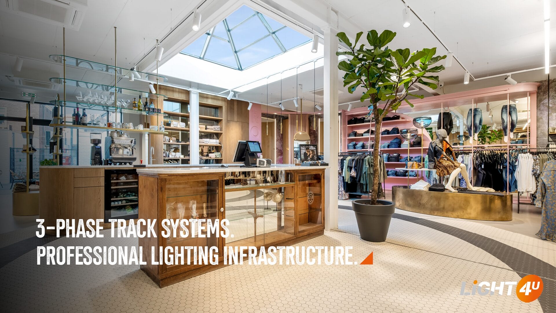
Track lighting systems are widely used in professional environments such as retail, hospitality, and office spaces. Among the available solutions, the three-circuit track system has become a standard because it combines electrical distribution, control, and flexibility within a single installation.
Rather than treating lighting as a fixed layout, this system allows luminaires to be organised, adjusted, and controlled in a structured way. To use it effectively, it is important to understand not only how it works, but also how it should be designed, specified, and installed in practice.
What is a three-circuit lighting track system?
A three-circuit lighting track system is a distribution system in which three independent electrical circuits are integrated within a single track profile.
The track contains:
- three phase conductors (L1, L2, L3)
- one neutral conductor (N)
- one protective earth (PE)
Each luminaire connects via an adapter that interfaces with these conductors. By selecting the phase within the adapter, the luminaire is assigned to one of the three circuits.
As a result, a single track can function as three electrically independent switching groups, without additional wiring.
Why is it used?
The system is used in professional lighting installations where control, load distribution, and flexibility are required within a single infrastructure.
Functional zoning within one system
The separation into three circuits allows lighting to be structured in layers.
- L1 → general lighting
- L2 → accent lighting
- L3 → feature lighting
Each group can be controlled independently. Therefore, the installation remains clear while the lighting concept gains more flexibility.
Load distribution across phases
Each circuit carries its own electrical load.
Instead of concentrating the total load on a single line, the system distributes it across three phases. Consequently, it reduces conductor loading, lowers the risk of overload, and helps to limit voltage drop over longer distances.
Typical configuration:
- ±16A per phase
- ±3.6kW per circuit
- ±10.8kW total capacity
This makes the system suitable for installations with many luminaires or higher power requirements.
Adaptability without rewiring
Because the circuit structure is integrated into the track:
- luminaires can be repositioned
- phase assignment can be changed
- lighting layouts can be adapted over time
All of this can be done without modifying the fixed wiring. Therefore, the system remains adaptable throughout the lifecycle of the project.
Circuit protection and operational continuity
Each phase is protected by a dedicated circuit breaker.
- protection against overload and short circuit
- continued operation of other circuits in case of failure
- possibility to isolate circuits for maintenance
However, the breaker rating alone does not define the final number of luminaires that can be connected. The maximum amount must always be checked against the selected circuit breaker type and the driver specification, or confirmed by the luminaire manufacturer.
If too many luminaires are connected to one circuit, the most common result is nuisance tripping during switch-on because LED drivers generate inrush current. In addition, uneven loading and unstable operation may appear over time if the circuit is not designed within a safe range.
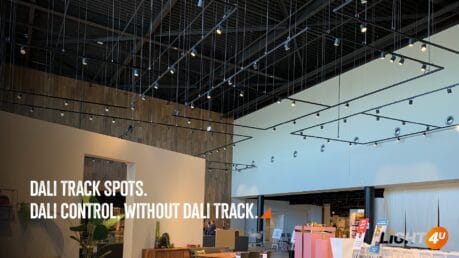
DALI and three-circuit track systems
When the installation requires DALI control, the standard three-circuit track is not sufficient on its own. In that case, a system such as 3-phase Pulse should be used.
Besides the regular power conductors, Pulse includes two additional conductors for the control signal. This allows the track to carry both normal input voltage and data for lighting control. As a result, the installation can support grouped or individual control strategies while keeping the mechanical advantages of the track system.
Even then, the electrical design still needs to respect phase loading, driver limitations, and circuit protection.
Design considerations for installation
The performance of a three-circuit track system depends on correct electrical and mechanical design. For that reason, careful preparation is essential.
Polarity and conductor alignment
The internal conductor layout is fixed and directional.
Therefore, installers should:
- install all track sections with consistent orientation
- use compatible system components
- maintain phase continuity throughout the installation
- check the polarity ridge before connecting sections and accessories
Otherwise, incorrect alignment can result in non-functioning circuits or electrical faults.
Mechanical continuity and track modification
Track sections must maintain both mechanical stability and reliable electrical contact. Therefore, every on-site modification requires care and system-specific handling.
When modifications are required:
- cuts must be precise
- connectors must be securely fixed
- internal conductor geometry must remain intact
In Nordic Aluminium track systems, cutting the track is only one part of the process. After cutting, the conductors must be bent correctly so the connection can function as intended. A dedicated bending tool is available for this step. If this procedure is not carried out correctly, the system may become unstable in operation, phases may fail to connect properly, or long-term reliability may be reduced.
Circuit breaker selection and load balancing
Each phase must operate within the limits of its protective device.
Therefore, designers should:
- consider breaker type, such as B-curve or C-curve
- respect the nominal current rating
- distribute luminaires evenly across phases
- verify the maximum luminaire quantity per breaker with the selected driver data
In this way, the installation operates more reliably and avoids unnecessary tripping.
Driver behaviour and inrush current
In many installations, the limiting factor is not steady-state power but inrush current from LED drivers.
At switch-on, drivers generate a short peak current. Therefore, too many luminaires on one circuit may trigger the breaker even when the connected wattage appears acceptable.
For this reason, the maximum number of luminaires should always be checked against:
- driver specification
- inrush current data
- circuit breaker type
- manufacturer guidance for the selected luminaire
Staying within a safe operating range is essential for stable system performance.
Attention to supply voltage
The supply voltage must always match the luminaire and driver specification.
If a luminaire intended for 230V or 240V is connected to 480V, the effect is not always an immediate visible failure. In practice, overvoltage can overstress the driver and internal components, accelerate ageing, damage insulation, and shorten service life significantly. After some operating time, this may lead to unstable behaviour, premature driver failure, or irreversible damage to the luminaire.
Suspension and structural support
The track must be supported according to the total system weight, the track length, and the installation conditions.
Based on the Nordic mounting table, the recommended fastening distance is 1000mm. Therefore, support points should generally be planned around every metre, while the exact fixing points should follow the selected track length and mounting detail.
The predrilled mounting-hole layout depends on the track length. For example, the table indicates an “a” dimension of 250mm, while the other distances vary depending on whether the selected track is 1000mm, 2000mm, 3000mm, or 4000mm long.
Therefore, the installation should include:
- sufficient suspension or fastening points
- appropriate spacing between supports
- secure fixation to the structure
This is especially important in longer layouts or installations with a higher density of luminaires.
Adjustability of suspension systems
Suspension systems do more than hold the track in place. They also allow the installer to adjust the track height and align the system accurately within the architectural space.
Consequently, the installation can respond better to ceiling conditions, design lines, and practical mounting requirements.
Feed-in strategy and voltage distribution
The track can be powered from different positions within the layout, depending on the project requirements.
Typical options include:
- end feed
- centre feed
- feed through connectors such as L, T, or X connections
For larger systems, multiple feed points are often recommended. This improves load distribution, supports voltage stability, and contributes to more reliable operation across the full installation.
System configuration and component selection
A three-circuit track system consists of several components that must function together as one system. Therefore, choosing the right parts is not only a matter of geometry, but also of electrical and mechanical compatibility.
Choosing the right components
A complete system typically includes:
- track sections
- connectors such as straight, L, T, or X pieces
- feed-in components
- suspension or mounting accessories
- luminaires with compatible adapters
To ensure reliable operation, all components should belong to one system, such as Nordic Aluminium GLOBAL Trac. This helps to maintain correct conductor alignment, mechanical fit, and electrical continuity.
Defining the electrical structure
Component selection should follow the electrical design of the project.
This includes:
- number of luminaires per phase
- load distribution across L1, L2, and L3
- driver specifications
- circuit breaker limitations
- required feed positions
- control method, such as standard 3-circuit or 3-phase Pulse for DALI
Therefore, the final configuration remains both technically correct and practically installable.
Using the Light4U Nordic Track Configurator
Because track configuration involves multiple variables, the design process can become complex. Therefore, a structured tool can make specification more efficient.
The Light4U Nordic Track Configurator helps users to:
- select the track colour
- define the track shape
- set the dimensions of the design
- determine the location for the power supply
- choose the mounting method
- download the final configuration
Afterwards, you can choose the required products from the catalogue and place the order through Light4U.
If you would like to use our configurator, please register via our partner portal. Once your account has been approved, you will receive a confirmation and can start using the configurator.
Conclusion
A three-circuit track system is a distributed electrical infrastructure, not just a mounting solution.
Its effectiveness depends on:
- correct electrical design
- proper component selection
- precise mechanical installation
When these aspects are aligned, the system provides a reliable and scalable solution for professional lighting applications in retail, hospitality, office, and exhibition environments.
If you need any further details or support, feel free to contact us!